Using butterfly valves for control


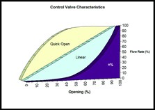
In an ideal world, the characteristic should be matched to the process conditions in order to give an installed gain of one across the entire flow range. In practise, the control valve has a useable range where the gain is between 0.5 and 2. Outside this range it is difficult to provide accurate control. By far the most widely used inherent characteristic is equal percentage.
Valves are often selected for economic reasons. This especially applies to butterfly valves. One of the reasons butterfly valves are selected is because they offer lower installation costs. Installation costs are lower because pipework reducers are generally not required as butterfly valves tend to be line size. In addition, butterfly valves use less metal in their manufacture making them cheaper to purchase and meaning they weigh less – which reduces the need for bracing or supports. Another reason people choose butterfly valves over other styles is because they can be more compact. This is especially important for vendors of package plant who will always try to reduce the overall envelope size of their equipment.
Typically butterfly valves are installed in secondary loops where control is not deemed as critical, or in loops where the pressure drop across a system must be limited and the designer needs a line-size valve with little or no obstructions to the flow path. Using a butterfly valve in these applications may not present any problems but all too often it will, and that is when the end user is faced with difficult choices. Butterfly valves inherently have a linear characteristic and in most applications have a useable controllable range between 25 percent and 50 percent of valve travel. They generally have a very high gain at low travel, which means that for a very small change in input signal there is a very large change in output. Trying to control at this lower end of the travel range results in set point under and overshoot. The valve gets a signal telling it to open, which it does, the resultant change in output is larger than intended so the valve gets a signal telling it to close, which it does, then it gets told to open, then to close… This opening and closing can create an oscillation in the loop that is reflected and then sometimes magnified in all connected loops. Operating at the other end of the travel range, when the gain is very low, you get little change in output for a large change in input. This makes the valve performance very sluggish. This problem is exacerbated when the loop has been tuned to restrict overshoot at low opening.
For some process operators this constant monitoring, re-tuning and process adjustment is not possible, so another option is to put the valve in manual control and set it to a single position. This is fine all the time the loop is in a stable condition, but it can create safety and/or end product quality problems if conditions elsewhere in the process mean that the valve should move. In these situations it is often necessary to look to change the valve to an alternative design.
However, once a butterfly valve is installed, especially on packaged plant, it may be very costly to re-engineer a solution using a globe or a ball valve. The pipework may need to be modified to take into account the longer face to face dimension and pipeline reducers may need to be fitted to account for the smaller body size. When a butterfly valve has been chosen due to limited available space then the modifications may be even more costly, with the possibility of having to move several pipes in order to install a valve with a larger envelope size.
An alternative solution has now been developed by Emerson Process Management - the Fisher® Control-Disk™ butterfly valve which has an equal percentage characteristic. This valve has been designed to offer better control in situations where a butterfly valve is the preferred option, or where it would be too costly to change a butterfly valve for another valve style. The effective control range of this new valve is very near to that of a globe valve. Tests have shown a useable control range of between 15 percent and 70 percent of travel, compared with the 25 to 50 percent for a conventional butterfly valve.
In keeping with Emerson’s other control valve designs, the new butterfly valve has been designed with maintenance in mind. Independent tests by valve maintenance staff have led to comments on how easy the valve is to disassemble and reassemble, without the need to stock discs and shafts as machined and matched pairs.
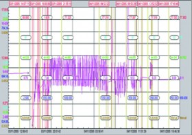
One of the companies that has been testing the new technology is Agfa Graphics Ltd. Agfa produce photographic film at their Leeds, UK site. In order to meet the production specification, the process temperature has to be kept to within ½ degree of the set point, of 44.5 deg C. The source water for the cooling system is taken from an outside storage tank. In the summer, the source water is generally above 15 deg C and the loop controlled well. In the winter, when the source water was below 10 deg C, the valve would move below its control range, down to around 8% open, and start to limit cycle. A limit cycle is caused when a signal is sent to the valve by the controller and due to the high gain at low travel there is a large change in flow rate when the valve moves. The controller quickly sends a signal telling the valve to change direction, which it does, causing a large change in the opposite direction. This cycling continues until either the process conditions change or there is some form of manual intervention.
When the original valve was unable to control, it had to be placed in manual and then adjusted any time there was a change in film width or production speed. It took time to get this adjustment right and large amounts of scrap were generated as a result.
Because Agfa was already using butterfly valves in this application, any change of valve design would have led to expensive piping modifications. In addition, they wanted to utilise the existing actuators and positioners. The valves were replaced with new Fisher Control-Disk valves, the control loop was switched to automatic and the improvement could be seen immediately.
The new Fisher Control-Disk valve, with its equal percentage trim and tested, proven reliability is destined to change the traditional approach to selecting butterfly valves for control applications.
Emerson Process Management, Tel: 0870 240 1978
Website: www.emersonprocess.co.uk

| Telephone: | 0870 240 1978 |
| Email: | uksales@emerson.com |
| Website: | https://www.emerson.com/en-gb/automation/home |
| More information on the Emerson Process Management Ltd BVAA Member Directory Page |
Search related valve / actuator articles: Emerson Process Management LtdIssue 11Butterfly ValvesMaster Class


