Preventing premature chemical dosing valve failure in subsea tiebacks

An eroded single stage valve

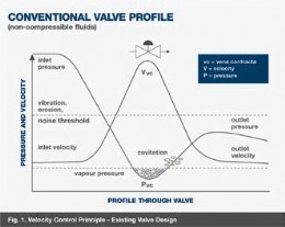
Fig 1; Velocity control principle - existing valve design

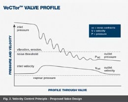
Fig 2; Velocity control principle - proposed valve design
One of the principal challenges in subsea systems is enabling flow assurance through effective hydrate management. To miminise the risks posed by hydrate formation, a continuous MEG injection will be required.
In recent times, Yorkshire-based Koso Kent Introl (KKI) was approached by a major oil operator, who required specialist assistance to overcome a hydrate management problem in an existing chemical dosing system within a subsea tieback.
Several manifold MEG dosing valves had failed prematurely within the chemical dosing manifold, and the operator was seeking an ongoing solution that would eliminate the risk of this occurring elsewhere in the system in the future.
KKI engineers were briefed about the problem: prior to the tieback being implemented, pressures in the pipeline had been relatively low (60 barg inlet pressure, with only a modest drop to 30 barg outlet pressure). The dosing valves had therefore been able to cope with the flow. With the introduction of a new, higher pressure well tieback to the field later in its life, inlet pressure had subsequently increased to 350 barg. The high velocities and energy levels arising from this greatly increased pressure drop had caused failures in the existing single stage valves well before the end of the commissioning period. Sand erosion was also a major problem, known to be contributing to the valves’ poor performance. The failure of the valves was causing costly, unacceptable interruptions to production in the field.
The KKI subsea engineering team are ever-mindful of the fact that the inaccessibility of any offshore site requires that system and components need to be designed for high reliability and low maintenance. In creating a suitable solution for the operator, KKI explored a wide range of application considerations, including rangebility, operating speed and retrievability.
The valve they proposed incorporated a multi-spline trim, with the flow sleeve and plug constructed as an insertable cartridge, allowing multiple stages of pressure drop to ensure that cavitation would not occur throughout the known flow range. The multispline trim option would be able to achieve the required rangeability of 200 to 1, due to the very precise fit of the plug within the seat.
The figures below illustrate the Velocity Control principle for the existing valve design, and for the proposed, multi-spline trim design.
The other major consideration was material selection. A range of scenarios were modelled, considering the effects of pressure drop for different materials at every stage of let-down, and determining long-term erosion rates for each. Materials considered included Inconel (cladding), various grades of Stainless, Stellite and Tungsten Carbide.
Guided by the KKI team, the operator selected the solid Tungsten Carbide option, and valve production took place at Kent Introl’s facility in Brighouse, Yorkshire.
Although the requirement was for a subsea application in this instance, the same benefits, of cavitation elimination, reduced maintenance frequency and prolonged life are equally applicable in severe service topside applications.
Koso Kent Introl
Tel: 01484 710311
Email: info@kentintrol.com
www.kentintrol.com

| Telephone: | 01484 710311 |
| Email: | info@kentintrol.com |
| Website: | www.kentintrol.com |
| More information on the KOSO Kent Introl BVAA Member Directory Page |
Search related articles: KOSO Kent IntrolIssue 30Repair and ServiceValve Repair and Service


