DP Flow: Treating of Automated Valve Assemblies as Engineered Products
What does the implementation of Recommended Practice S2812-X-19 or ISO/TC 153 N 425, ISO/NP 5115 in practice mean for the various groups involved such as valve and actuator manufacturers, integrators, and end-users of automated valve assemblies?
ANDREAS VOGT F.I.R.S.T. GESELLSCHAFT FÜR TECHNISCH-WISSENSCHAFTLICHE SOFTWAREANWENDUNGEN MBH
In June 2019, the "Recommended Practice S2812-X-19" (hereinafter referred to as RP) was published by the WIB at the Valve World Americas Conference in Houston. The RP is entitled "Actuated Valve Assembly - A Recommended Practice for Part turn Automated On-Off valves" and addresses the issue (including the definition of the general conditions) of sizing, selection, and the mechanical integrity of automated valve assemblies widely used in many industries.
Since F.I.R.S.T. has comprehensively supported the development of the RP both in principle and with functional prototypes, it is a matter of course that a module will soon be available in CONVAL® that fully maps the RP. Recognizing the importance of the issue for the worldwide community, the ISO has taken up the task of developing an international ISO standard with RP as a basis. At this point, the ISO even goes one step further than the RP in considering electric actuators, as the RP is limited to pneumatic (and in a broader context hydraulic) actuators.
I have already published a paper on this topic in Industrial Valves , so I will not go into all the details of the RP here but only give an overview. The focus will be on the requirements for the implementation of the RP in practice, from the various perspectives. The viewpoint of the manufacturers of the valves, the actuators, possible integrators as well as that of the end-users.
Recently I gave two webinars on this topic at the virtual "Forum Industriearmaturen" and during the introduction, I made a small poll among the participants. Each one of the webinar participants confirmed that they had cases of valves in their practice that did not open or close when required or even sheared off the stem. For me a clear indication of the importance of the topic for the industrial valve user community.
If one were to summarise the objectives of the RPs in a few sentences, it could be described as follows:
If you automate rotary valves as shut-off valves, you have to find the right actuator for the required torque, which is derived from the valve and application data.
- On the one hand, this actuator should have enough torque and an adequate safety margin to operate the valve safely under all expected conditions
- On the other hand, it should not be oversized, and not just for cost reasons. It must not be designed in such a way that the torque delivered may damage the valve, seat, or stem
- The design should take into account all relevant data and conditions of the equipment used and the application itself
- The selection made should be documented comprehensively, completely, and uniformly so that it can be traced at any time
When you look at the RP it quickly becomes clear that the approach described makes perfect sense by itself, but immediately raises many more questions and demands on the groups involved. I have already outlined these in the DIAM 2019 lecture program. It should not be forgotten that RP was initially conceived from the perspective and driven by the needs of end-users in the process industry. However, to implement it, a profound acceptance, transparency, and openness on the part of the manufacturers of actuators and especially valves are required.
But first to the question "Why all this?”. In short, because today automated valves are not treated as "Engineered Product". Safety, application, and possible further factors remain unclear and the procurement of valve, coupling, and the actuator is often in different hands. As a result, they are not considered as assemblies and responsibilities for the final delivered solution often remain unclear.
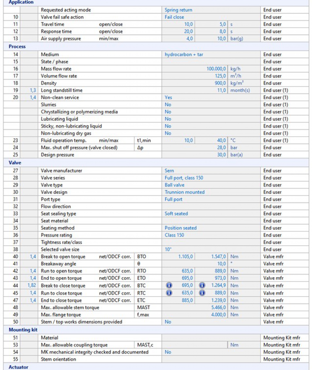
The RP clearly defines the responsibilities for the required data and keeps them in the documentation, the "Automated Valve Data Sheet". There (extract in Figure 1), the right-hand column clearly shows who is responsible for the data.
Nothing is surprising on the end-user side, the data can all be obtained from the process engineering department and the valve manufacturer. However, if you want to choose a suitable actuator, you will need a lot more information about the valve, the mounting kit, and the potential actuator.
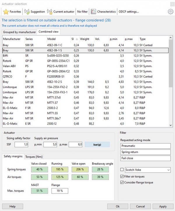
Ideally, as implemented in CONVAL®, the requirements of the process are specified, supplemented by information on factors (media properties, long standstill times, etc.) that could further influence the torque requirement, a valve is selected from the database and, after entering a safety factor for the design, the appropriate actuator can be selected.
This ideal case, however, requires that valve and actuator manufacturers have determined and published the required key parameters of their devices and that these are also stored in the database. Of course, manual input is always possible if the data is not available in the database.
On the actuator side, this is standard, usually the data on torques, flange design according to ISO 5211 , etc. are published in full. Even if these have not yet been captured in the database, the entry is quickly completed with just a few values, taken directly from the documentation of the actuator manufacturer.
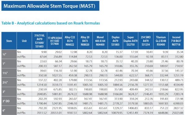
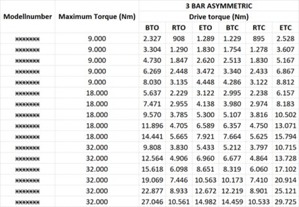
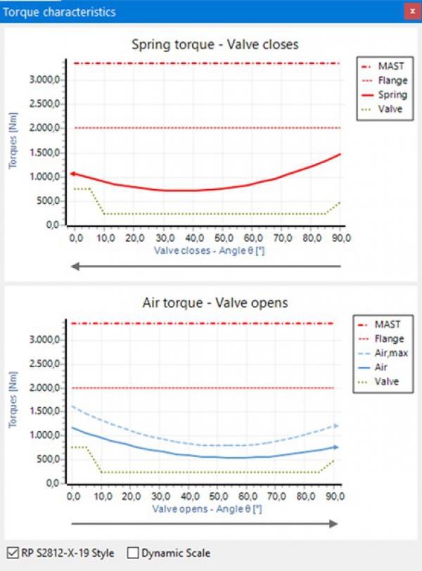
With the valves, the situation is different for a variety of reasons. Things like the MAST (Maximum Allowable Stem Torque) can still be found, depending on the stem material (example Figure 2), as they are more or less easy to calculate by the manufacturer. The flange class according to ISO 5211 is also no problem. However, RP still expects, for the calculation of the required torque of the valve, six different torques (as shown in Figure 3 as an example) matching the differential pressure. Furthermore, a breakaway angle as well as correction factors for the application are required.
Sometimes, however, the maximum torque is the only information available. There are rules of thumb (for each valve style) like e.g. BTO, ETC = 100%, RTO, RTC=40%-50%, ETO, BTC=70%, but these should be used with caution and do not conform to the RP or the upcoming ISO standard.
In practice, however, there are unfortunately hardly any publicly available and fully documented torques, so that there seems to be a considerable backlog demand on the part of the valve manufacturers.
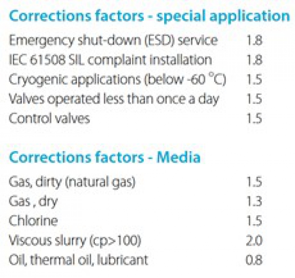
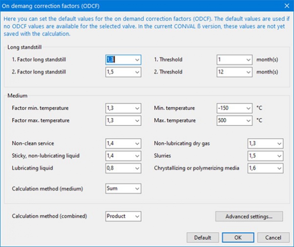
The situation is similar for the correction factors for the application conditions (defined as ODCFs in the RP). Some manufacturers specify factors for different situations (example Figure 4), but these do not necessarily correspond to the system of factors in the ODCFs and certainly do not define how to proceed when several factors come together (add, increase, multiply, etc.).
As defined by the RP, CONVAL® allows each manufacturer of valves to configure these factors for each valve series and to define how they are handled individually. This applies to the factors and their application limits (see Figure 5) as well as to the question to which torque the factor should be applied (see Figure 6). For example, by default (RP recommendation) the factor for long standstill times for the safety function "spring closes" is only applied to the BTC, for "spring opens" only to the BTO.
Tel: +44(0)1865 600245
Email: sales@dp-flow.co.uk

| Telephone: | 01608 544222 |
| Email: | sales@dp-flow.co.uk |
| Website: | https://www.dp-flow.co.uk/ |
| More information on the DP Flow Ltd BVAA Member Directory Page |
Search related articles: DP Flow LtdIssue 58Standards


