
Practical use of Detonation Flame Arresters


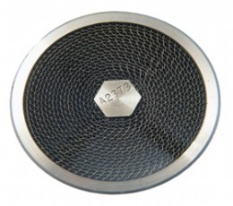

Table 1: Typical MESG and Gas Groups according to ISO 16852:2008
Proper design of explosion prevention and protection systems, coupled with rigorous operating and maintenance procedures should ensure that the possibilities of getting a flammable gas/vapour and air mixture in many process are remote, and the chances of it igniting are remoter still. But in storage tank venting and vapour collection systems the risks are greater, so the proper use of flame and detonation arresters is paramount in ensuring the safety of a plant during its operational life.
What is a detonation?
In this context detonations are to be considered in open or closed piping systems, such as vent lines or vapour collection systems, when long lengths of piping are involved. When a gas/air mixture is ignited within the confines of a pipe the resultant increase in volume of the burning mixture causes the un-burned mixture ahead of it to be pre-compressed and acceleration of the flame front occurs as the rate of combustion increases. The early stage of this process is termed a deflagration, where flame speed is sub-sonic and the pressure wave travels well ahead of the flame front; typically flame velocities are less than 100 metres/ sec with pressures below 0.1 MPa g for explosions initiated under ambient conditions, but can be 200- 300 metres/sec and 1 MPa g towards the transition to detonation. As the combustion process further accelerates eventually the flame front and pressure wave come together resulting in the formation of a high pressure shock wave in the so-called Deflagration to Detonation Transition (DDT) zone. This shock wave exists only marginally ahead of the flame front.
This zone is also characterised by an overdriven or unstable detonation where the severe shock wave compression can give transient pressures well in excess of 15 MPa g and flame velocities over 3000 metres/ sec. The magnitude of these shock waves dissipate quickly and the detonation wave then becomes stable, with pressure around 2 to 3 MPa g and typical flame velocities between 1600 and 2000 metres/sec.
Detonations can only occur within certain gas/vapour concentrations; usually these are within the normal flammable range of the material in question. Towards lean or rich limits a phenomenon called a galloping detonation can occur. This can also occur when flame speeds are temporarily decayed to those in the deflagration zone by changes in direction (bends, elbows etc.) This basically means that a flame front can repeatedly fluctuate between deflagration and stable detonation via the DDT/unstable detonation zone: an extremely dangerous occurrence.
It is important to emphasise that a stable detonation event can only occur after an unstable detonation has occurred. The point at which these events occur is heavily dependent on pipe diameter, piping configuration, pipe type (e.g. smooth welded, or rough with flanged joints), gas/vapour type, gas/vapour concentration in air, operating temperature and operating pressure. Only in controlled laboratory conditions with stoichiometric test gases can the position of these events be predicted with some certainty. In process plant it is far more likely that gases/vapours other than the standard test gases (propane, ethylene or hydrogen) will be handled, in concentrations towards the lean or rich limits of flammability and in pipe containing numerous bends, valves etc. These factors will affect how explosion protection, in particular detonation arresters, is applied.
How do detonation arresters work?
Cell type detonation arresters utilise the small cells together with an optimum cell length to provide a large surface area for heat transfer. Heat from burning gas is dissipated through the boundary layer within the cells and is eventually cooled to below its auto-ignition temperature. The size of cell required is dependent on the actual gas/vapour and may be defined using a fundamental property of all flammable gases/vapours - the Maximum Experimental Safe Gap (MESG).
Stable Detonation Arresters
The use of stable detonation arresters, whilst common practice in Germany and recognized by ISO16852:2008, is fundamentally flawed because it totally ignores the presence of DDT/unstable detonations and galloping detonations, seemingly relying only on accepted levels of risk. Moreover, manufacturers of such devices do not necessarily make the risks involved in using these detonation arresters obvious to the user.
As an analogy consider a fundamental explosion prevention technique of maintaining the gas/air concentration at 25% of the lower explosion limit (LEL). It could be considered equally acceptable to maintain at, say, 25% above the upper explosion limit (UEL), but because the full flammable range has potentially to be passed through to reach this, it would not normally be considered good practice. So why use stable detonation protection when an unstable state has to be passed through first; this level of risk is totally unacceptable.
ISO16852:2008 (paragraphs 7.4.4, 11.1h and Annex D) tries to overcome this by not allowing the use of stable detonation arresters in isolation, and associated levels of protection in Zone 0, Zone 1 and Zone 2 areas (typified by the German TRbF 20 regulations). The fact is if a detonation can occur it will take no notice of whether it is in Zone 0, 1 or 2, the end result is the same.
Stable detonation arresters are built to lower standards than the unstable types and when subjected to the DDT/unstable zone will be often be mechanically destroyed because of the extremely high dynamic loads exerted with unstable detonations for which they are not designed (See How Safe is the Process Piping later in this article).
Unstable Detonation Arresters
For most of the world only unstable detonation arresters are considered acceptable, e.g. the United States Coast Guard Standard, when testing for both stable and unstable detonations, only permits the use of arresters that have been certified for both. Because of the unpredictability of detonation events in practice no other device can give the universal protection without the need to consider possible location and use of additional protective systems. One criticism of unstable detonation testing is the inherent unpredictability and wide range of flame speeds and pressure which may be measured compared to stable detonation testing (where these parameters can be calculated from theoretical principles). However, considering the number of tests carried out, this surely gives a more robust solution than risking a much lower performance stable detonation arrester. After all it would never be acceptable to use a deflagration arrester instead of a detonation arrester because the chances of it seeing a detonation are very small.
Unstable detonation arresters may have higher pressure drops compared to their stable counterparts, however, considering that stable types may have to be used in duplicate or with a deflagration arrester this issue is in reality of no concern. Such factors as flow capacity and pressure drops need, in any case, to be considered during the design stage of a process, although in reality are often considered only as an afterthought, thereby causing unnecessary practical and cost problems.
Detonation Arresters subjected only to Deflagration Events
The fact that a detonation arrester is used does not necessarily mean that it will always be subjected to a detonation. Considering the effects of, for example, lean/rich vapour/air mixtures, only a deflagration may result from an ignition of the mixture. Unless rigorously tested there is the possibility that a detonation arrester can fail when subjected to a deflagration flame front. Both the USCG and ISO16852:2008 test protocols allow for testing of detonation arresters with restricted outlets. With USCG this is mandatory, whereas in ISO16852:2008 it is optional, leading to an unnecessarily large number of detonation arrester types. A restricted outlet refers to, for example, a partially closed valve or elbow immediately on the protected side of the detonation arrester. In a deflagration, the pressure wave is ahead of the flame front; such a restriction may cause a back pressure before the flame front has actually reached the detonation arrester, causing the gas then to burn at a higher pressure to that for which it may have been certified and the flame will pass through the detonation arrester.
Relocating the valve or elbow etc. further from the detonation arrester will eliminate this potential problem, but far better is to certify the detonation arrester to allow for restricted outlets.
Effect of Elevated Temperatures and Pressures
Detonation arresters are often used in applications where the process is operating at temperatures and pressures higher than ambient/atmospheric; these are typically up to 60°C and 0.01 MPa g. In such cases it has to be determined what the conditions are under which a gas or vapour/air mixture can ignite in a given process. For example, unless air at the same pressure is available in a high pressure gas relieving vent, the only time when the detonation arrester has to function is when air and gas can mix, probably at atmospheric pressure, when the relieving gas pressure has decayed allowing back mixing with air. At elevated pressures more energy is developed and flame acceleration is more rapid, so explosion pressures are higher (roughly in direct proportion to the initial pressure at ignition) and the DDT zone will be reached in a shorter pipe length.
In any case if gas/air can be present at elevated pressure and/or elevated temperature it is essential that any detonation (or in-line deflagration) arrester has been tested and certified for use under these conditions. ISO16852:2008 has apparently arbitrary limits of 150°C and 0.06 MPa g, but arresters are certainly available for higher temperatures and pressures. Considering that such arresters may have higher pressure drops and be more expensive it is vital that the process is evaluated carefully to avoid unnecessary problems.
Stabilised Burning
Stabilised burning is a phenomenon that can occur when a flame arrester is passing flammable mixtures of gas/vapour and air which can ignite and, because of the flow rate, continue to burn on the surface of the flame arrester element. It is more likely to occur during uncontrollable venting of atmospheric storage tanks and flame arresters used in such applications often need to be endurance burn proof, which means that they can withstand premixed burning for an indefinite period. According to regulations such as TRbF 20, using detonation arresters with a suitably long vent pipe can ensure that burning cannot occur on the arrester element. The validity of this is suspect since it assumes the detonation arrester will always be subject to a detonation, whereas in practice a deflagration is just as likely to occur.
Of course, stabilised burning can also be possible with in-line applications, such as vapour recover installations, and the detonation arresters used must be capable of handling such events. Whilst endurance burn proof detonation arresters are available, their use in isolation (as with all endurance burn proof flame arresters) has to be questioned since it effectively allows an undetected fire to burn in a hazardous area without any action; during testing the unprotected side of the arrester housing may be glowing red, making nonsense of the hazardous area temperature classifications! Far better and safer is to fit temperature monitoring equipment so that appropriate action to stop the burning can be taken in the shortest possible time. Fitting temperature sensors is, in any case, essential if the detonation arrester can only withstand burning for a limited period and such an event is possible in the process concerned. ISO16852:2008 requires the stabilised burning time to be clearly labelled on the flame or detonation arrester.
How Safe is the Process Piping?
A frequently asked question concerns the suitability of normal process piping if detonations can occur within them. In simple terms a flame front/detonation travelling down a pipe is not to be considered a static pressure (although piping should be able to withstand the normal static explosion pressure, so 1 MPa g rating at ambient conditions, for example), but a dynamic shock pressure which only acts on the pipe walls for milliseconds. By far the greater danger is the momentum and energy effect of the flame front/ detonation when its progress is interrupted by, for example, pipe bends, valves and flame/detonation arresters. When this momentum/energy is transferred it can result in a catastrophic failure unless this equipment is designed to withstand such forces. For this reason deflagration and stable detonation arresters will fail mechanically (as well as pass flame) if subjected to DDT/unstable detonation forces. The location of such fittings/vales must be considered carefully, adequate support provided and unstable detonation arresters placed strategically to minimize the risk of mechanical failure in the piping.
Summary
It is dangerous to assume that a detonation arrester, without qualification as stable or unstable type, can provide full protection in the event of an ignition of flammable gases/vapours in piping systems. Using stable detonation arresters in isolation potentially puts lives and multi-million dollar process plant at risk because stable detonation arresters:
Only protect against deflagration and stable detonations;
Have fundamentally flawed limitations on location;
Do not protect against galloping detonations;
Must be used together with other protective systems.
Only unstable detonation arresters can provide full protection against deflagrations, stable, unstable and galloping detonations without limitations on location.
Referenced and Other Relevant Standards
ISO16852:2008 Flame arresters - Performance requirements, testmethods and limits for use.
TRbF 20 Technische Regeln für brennbare Flüssigkeiten (Regulations for the handling of flammable liquids).
USCG United Stated Coast Guard CFR 33 Part 154 Appendix A.
EN 1127-1: 2008 Explosive Atmospheres Explosion Prevention and Protection Part 1: Basic Concepts and Methodology.
Tyco Valves & Controls
Tel: 01224 722562
Website: www.tycovalves-eu.com
![]()
| Telephone: | 0870 240 1978 |
| Email: | uksales@emerson.com |
| Website: | https://www.emerson.com/en-gb/automation/home |
| More information on the Emerson Process Management Ltd BVAA Member Directory Page |
Search related valve / actuator articles: Emerson Process Management LtdIssue 18Master Class
Recent magazine news articles

I have shamelessly stolen this wonderful phrase from a very good friend of the ...

As the UK water industry enters Asset Management Period 8 (AMP8) from 2025 to ...

For valve designs in biogas plants and for upgrading biomethane and CO2, ...

Our planet's water resources are facing increasing challenges. The growing ...
-web.jpg)
At AFFCO Flow Control UK, we are dedicated to delivering engineered solutions ...

OEM Automatic, a leader in industrial automation products, remains at the ...

The BVAA is hosting a Regional Dinner on 12 March and a Supplier ...

The global energy sector is undergoing a significant transformation, and events ...